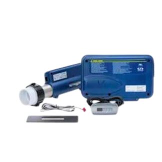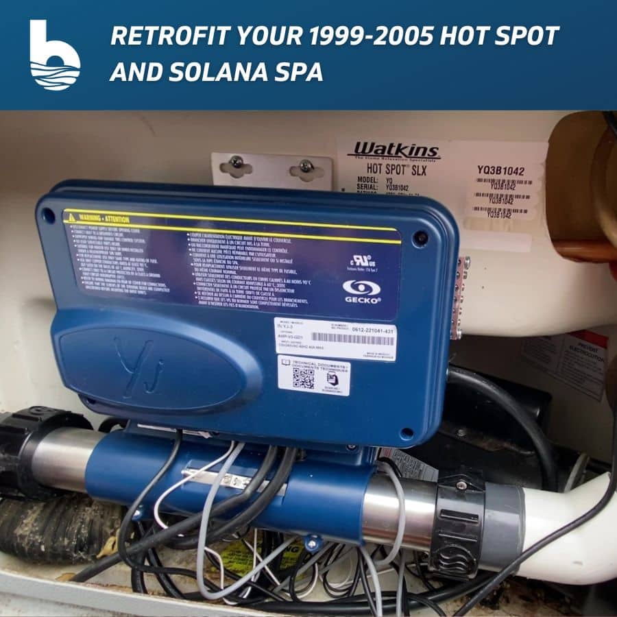
Welcome to Backyardplus! In this post we are going to show you how to retrofit your 1999-2002 Hot Spot RE, RLX , SE, SLX, and 2000-2005 Solana RX, SX, TX with the Gecko YJ3 control box, Gecko KN200 Keypad and the Gecko Heat.Wav heater. Before we get started, let’s go over the tools and parts you will need.
If your topside control panel is the same size as the ones in these photos (approximately 4.5 inches wide), this retrofit kit should work in your spa.
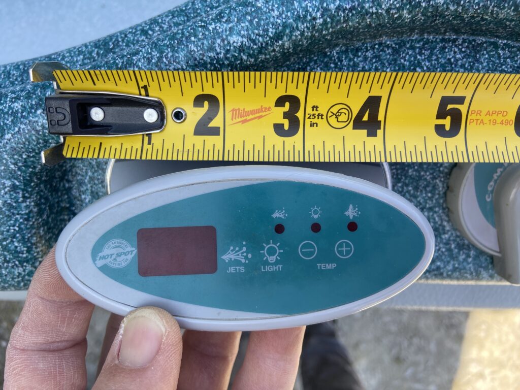
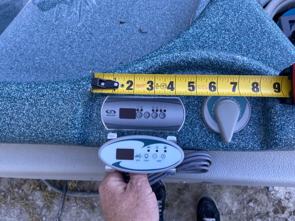
Tools you will need:
- Phillips head screwdriver
- Small flat head screwdriver
- Scraper
- Needle nose vice grips
- Pliers
- Channel locking pliers
- Black Sharpie
- Drill
- Silicone grease
Parts you will need:
- Gecko IN.YJ-3 Series Complete System, Item #: 77726-BUNDLE
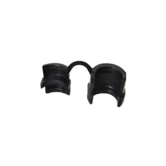
- Strain Relief 1/2in, item #: 36022
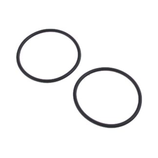
- Compression Fitting O-rings, for 2in Union, item #: 34447-x2-BYP
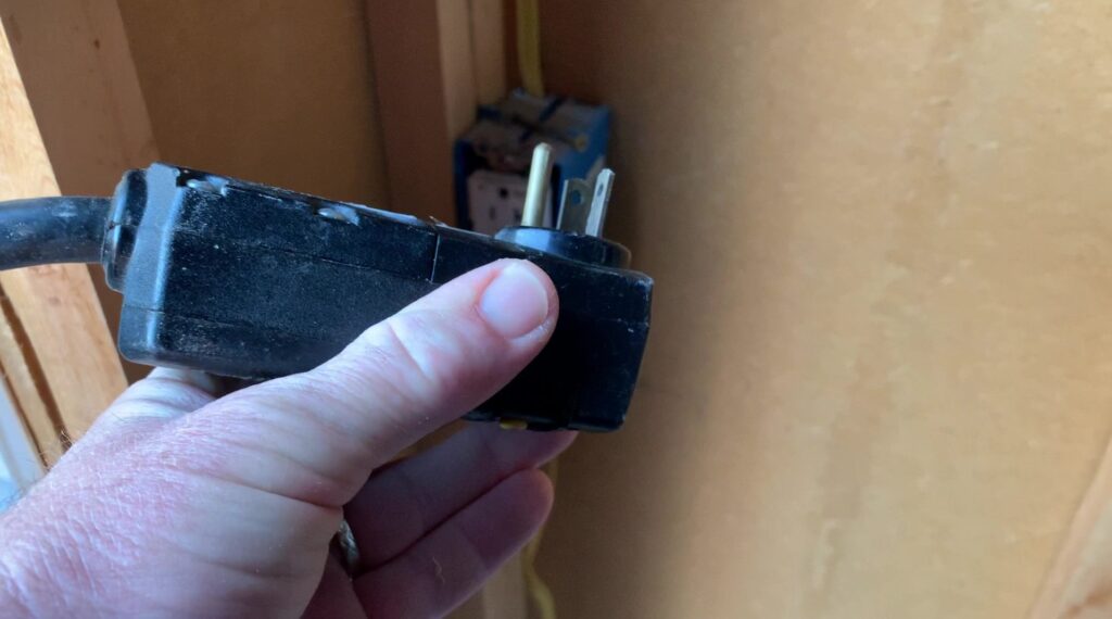
Step 1. Disconnect power from the spa.
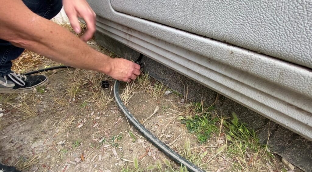
Step 2. Drain the spa.
Step 3. Remove the equipment door and control box lid.
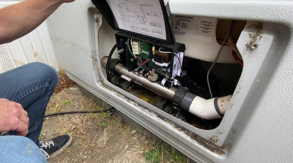
Step 4. Disconnect the incoming power, spa light, jet pump, temperature sensor, and the topside control panel from the control box.
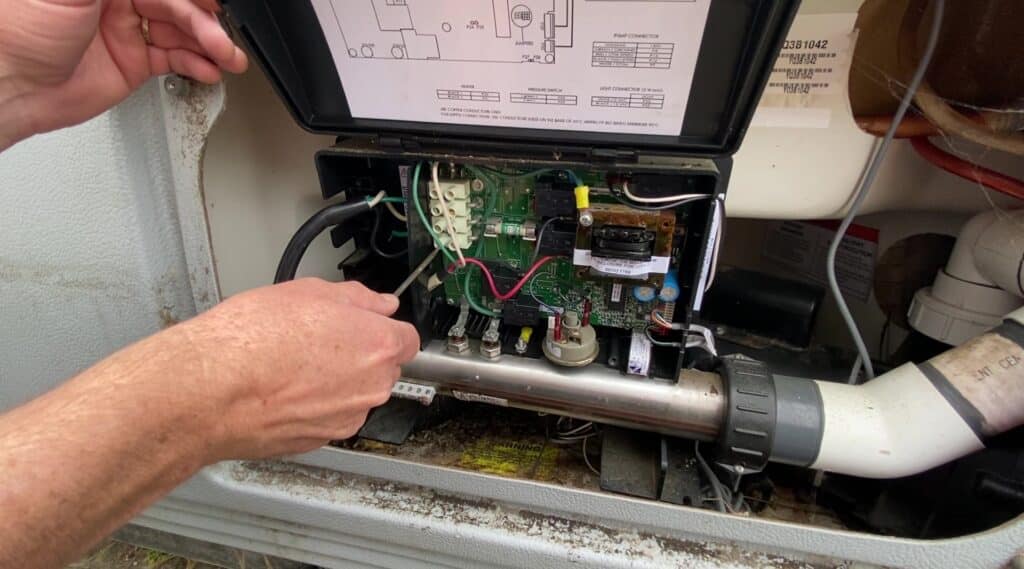
Disconnect the spa light.
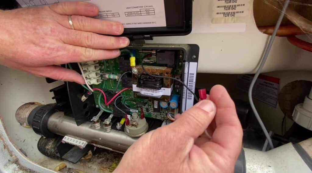
Disconnect the jet pump.
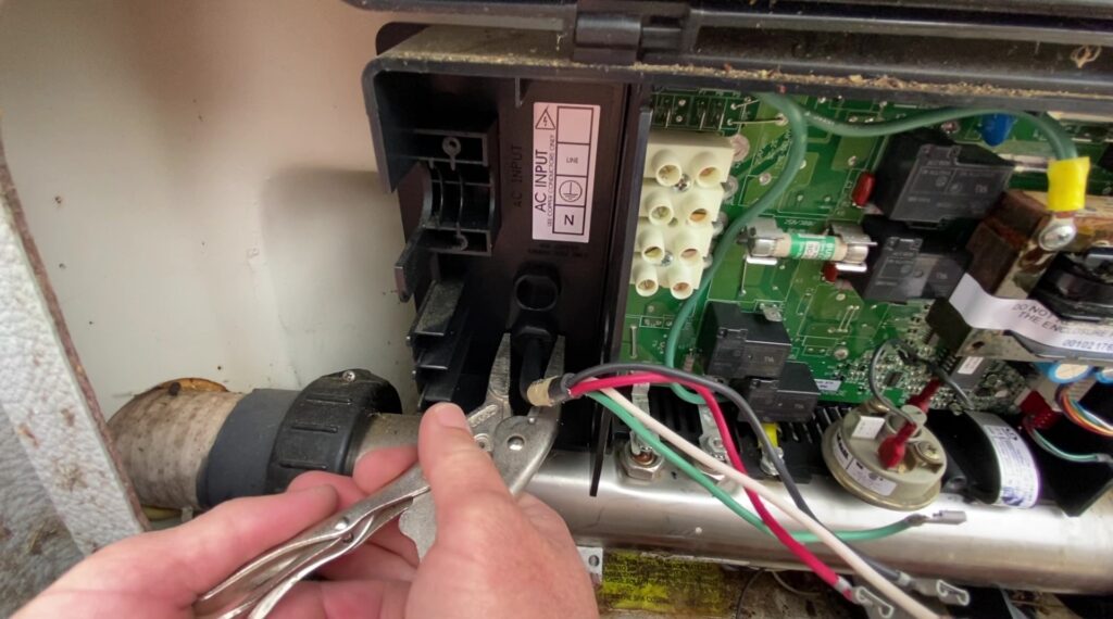
Disconnect the temperature sensor.
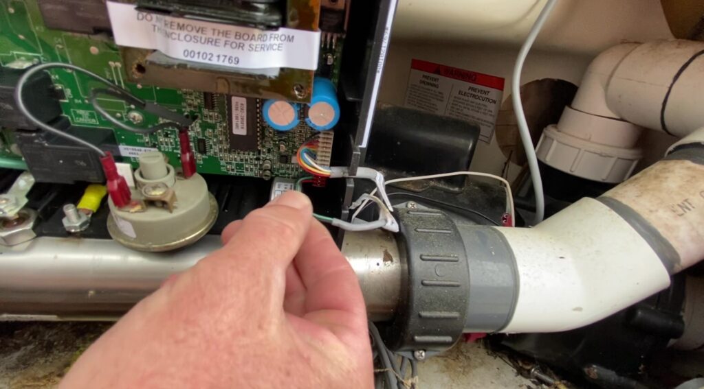
Disconnect the topside control panel.
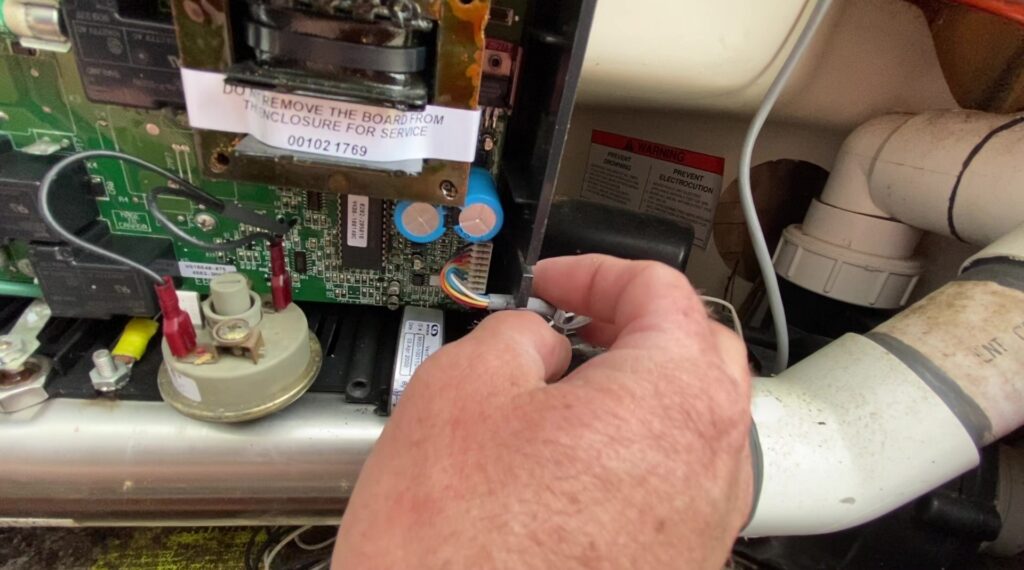
Step 5. Loosen the heater compression fittings and remove the entire control box and heater from the spa.
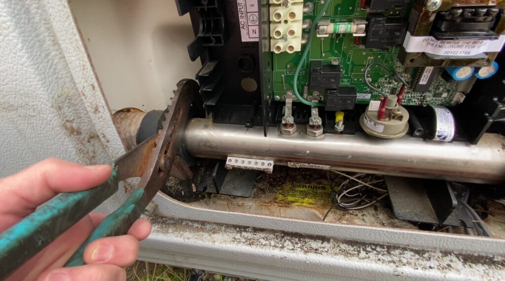
Remove the control box and heater.
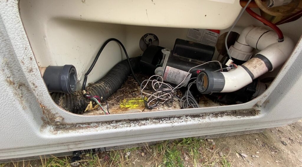
Step 6. Remove the topside control panel from the spa by loosening the wing nuts underneath the bartop that hold it in place.
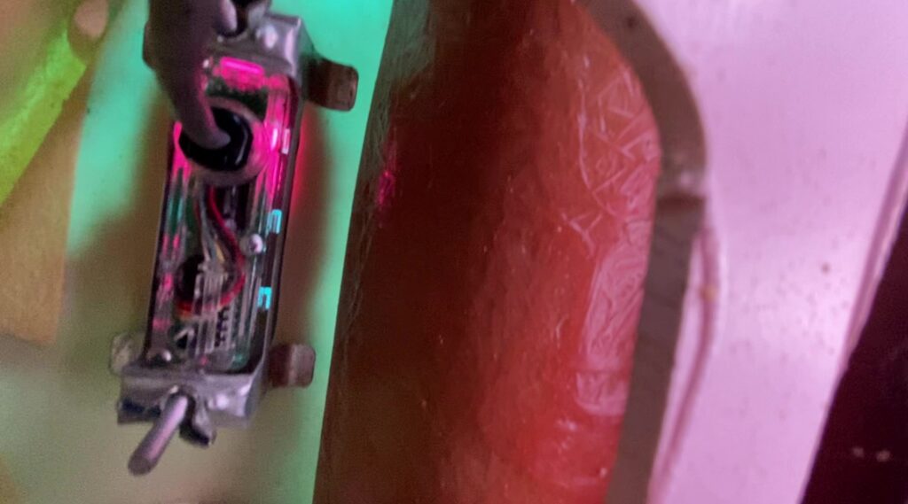
Remove the topside control panel.
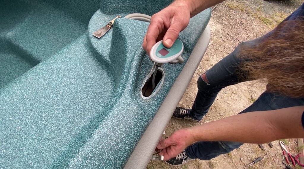
Step 7. Remove the spa light connector from the light fixture by turning it counterclockwise.
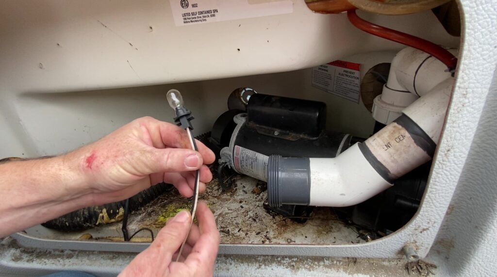
Step 8. Keep the original temperature sensor in place in the filter compartment.
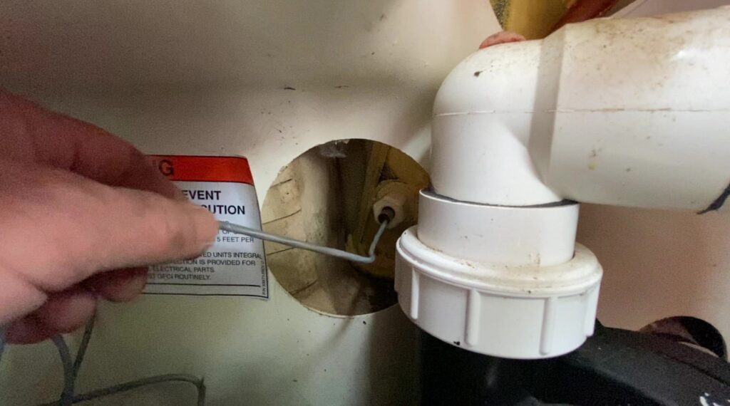
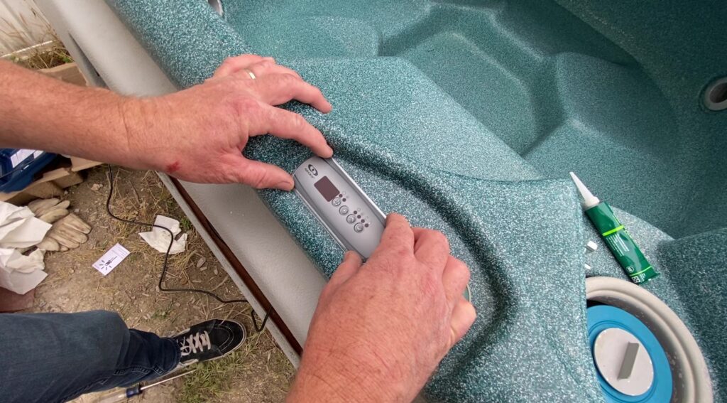
Step 9. Use a scraper to remove the residue from the old topside and install the new K-200 topside control panel in the bartop.
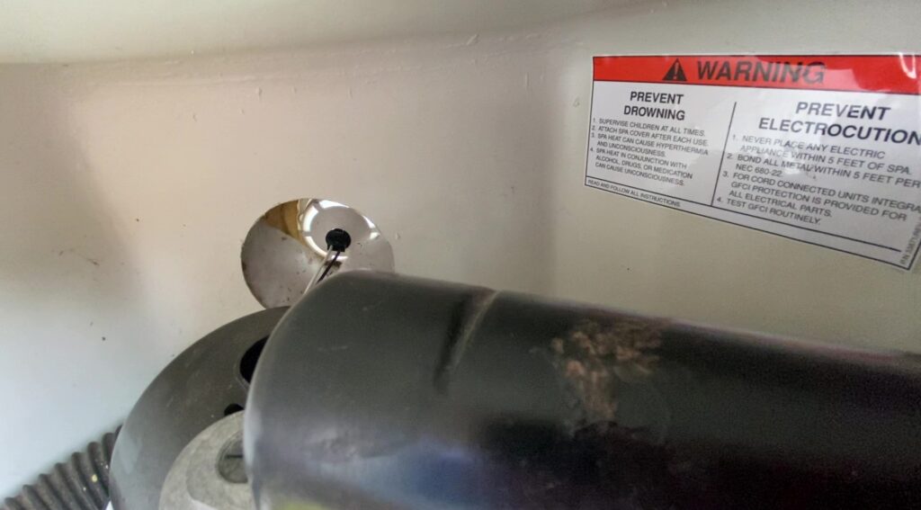
Step 10. Install the new LED light by inserting the connector into the light fixture and turning it clockwise about a quarter of a turn.
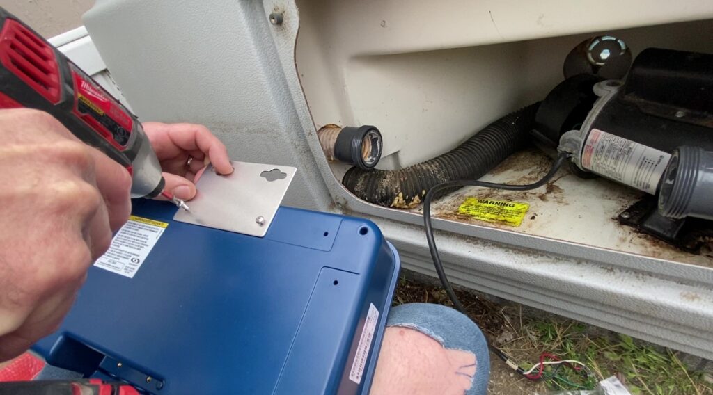
Step 11. Install the provided mounting bracket on the YJ-3 box with the two screws and determine the best location to mount the box with the heater remaining in the upright position.
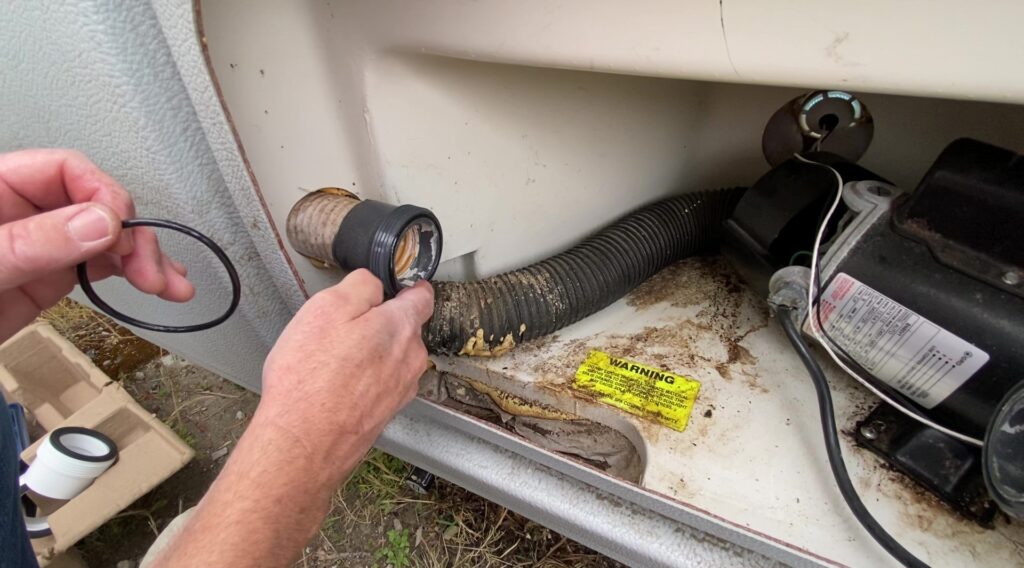
Step 12. Remove the old compression O-rings. Cover the new O-rings with silicone grease and install them.
Step 13. Install the new Heat Wav heater in the upright position.
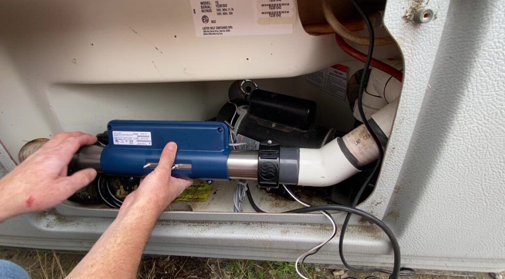
Step 14. Mark the location for the control box mounting screws with a Sharpie. Drill the holes without going too deep (you don’t want to puncture the shell). Insert the mounting screws and mount the control box on the wall.

Step 15. Connect pump 2 (the one speed pump). Connect the black hot wire to K-5P, white neutral wire to P19 and green ground wire to P28. If you don’t have a pump 2, go ahead and remove the connector.
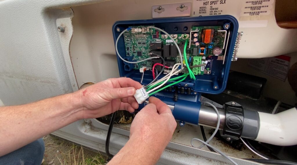
Step 16. Connect pump 1 (the two speed pump). Connect the red low speed wire to K-6P, black high speed wire to K-7P, white neutral to P20 and green ground to P29.
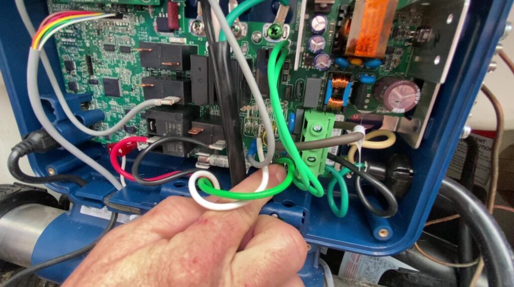
Step 17. Connect the ozonator (if you have one). Connect the ozone black hot wire to P23 or P39, green ground wire to P30, and white neutral wire to P35. If you don’t have an ozonator, go ahead and remove the ozone connector.
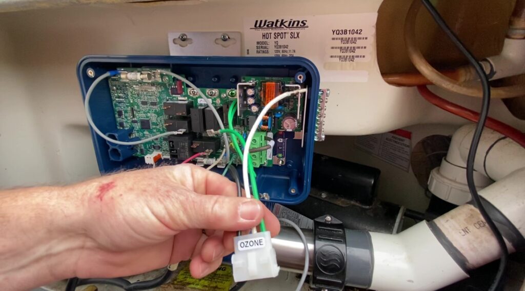
Step 18. Connect the heater. Connect the black hot wire to P3, white neutral to P4, and green ground to P5.
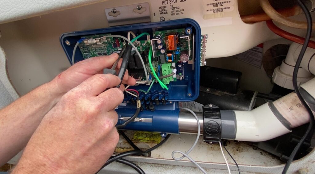
Step 19. Plug the heater sensor cable into P1.
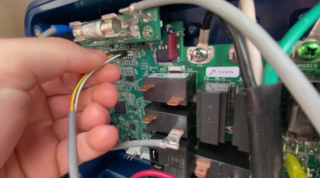
Step 20. Plug the LED spa light into P33.
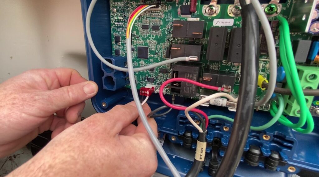
Step 21. Plug the K-200 topside control panel into P22.

Step 22. Connect the incoming 115 volt power wires. Squeeze the strain relief bushing around the power cord with your needle nose vice grips and install it on the right side of the control box. Connect the white neutral wire to N, black hot wire to L1, and green ground wire to the green arrow on the terminal block. For 115-volt operation, keep the brown jumper wire connected to L2 and P21. For 230-volt operation, remove the brown jumper wire from L2 and P21, and connect the second hot leg to L2. The heater will run at 230 volts, but all other components will continue to run at 115volts.
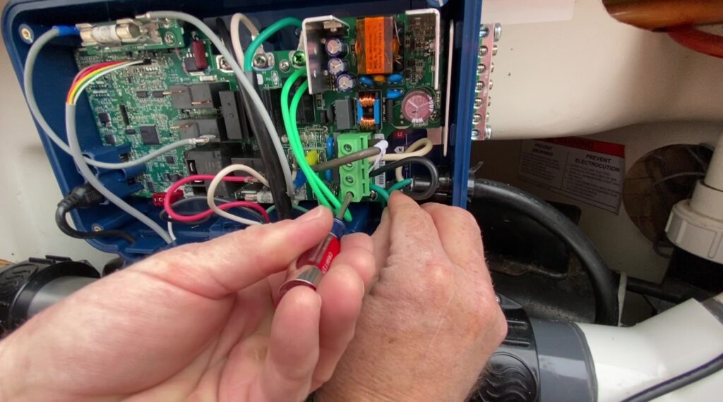
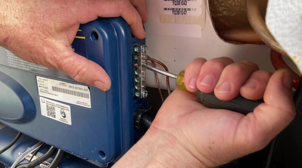
Step 23. Connect the copper bonding wires from the jet pump and the heater to the bonding terminal on the control box.
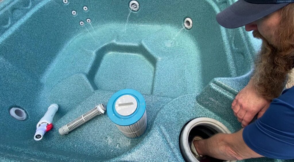
Step 24. Refill the spa by removing the filter and filter standpipe and inserting the garden hose into the standpipe fitting. Turn the water on full blast and wrap a rag around the hose to force all air out of the lines. After 2 or 3 minutes install the pre-filter on the garden hose and finish filling the spa.
Step 25. Connect power to the spa. The display sequence at every startup will be lamp test, software number, software revision, and low-level selected. The display will show three dashes during flow verification. If the flow is sufficient, the temperature of the water is displayed on the keypad screen.
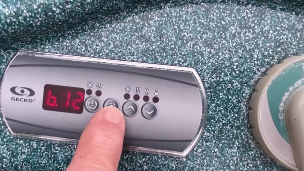
Now let’s program the breaker settings. Press and hold the light key (for about 20 seconds) until you reach the breaker settings menu. The filter cycle duration menu will come up first. Keep holding the light key down until you reach the breaker settings menu which will appear as b.24.
The values displayed by the system correspond to 80% of the maximum amperage capacity of the GFCI. Use the Up or Down keys to choose the desired value. For example: If you are using a 15A breaker, select b.12. If you are using a 20A breaker, select b.16. If you are using a 50A breaker, select b.40. In this case we are using a 15A breaker, which means we will select b.12. Press the light key to set the breaker rating.
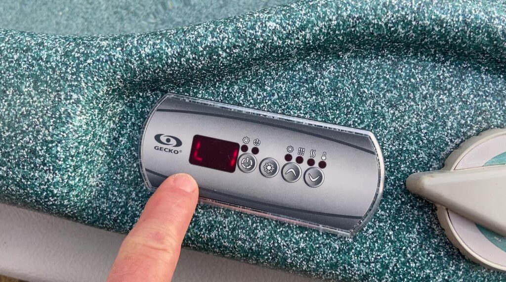
Step 26. Program the low-level configurations. At startup the display should read L1 for spas with a single 2-speed jet pump. If the display does not read L1, or your spa has more than one jet pump, go into the low-level configurations menu. Press and hold the Pump 1 button for 30 seconds. Use the Up/Down keys to select the new low-level configuration. Select L1 for spas with a single 2-speed jet pump. Select L3 or L8 for spas with two jet pumps. Press the Light key to confirm the low-level configuration. The “Pump 1” indicator light will flash when pump 1 is on at low speed.
Step 27. To set the filter cycle duration and number of cycles in a 24-hour period, press and hold the light button down for 5 seconds until you see the letter d. Use the up and down keys to select the duration of the filter cycles in hours. Press the light key again to select the number of filter cycles per day. Press the light key again to choose C (Celsius) or F (Fahrenheit). Press the light key to return to the main menu.
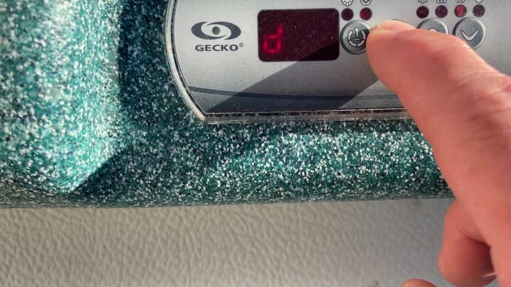
Step 28. Test the LED spa light. The light icon will turn red when you press the light key. Tip: If the LED light fails to come on, power off the spa and turn the bulb around in the harness. The LED light will only work in one position.
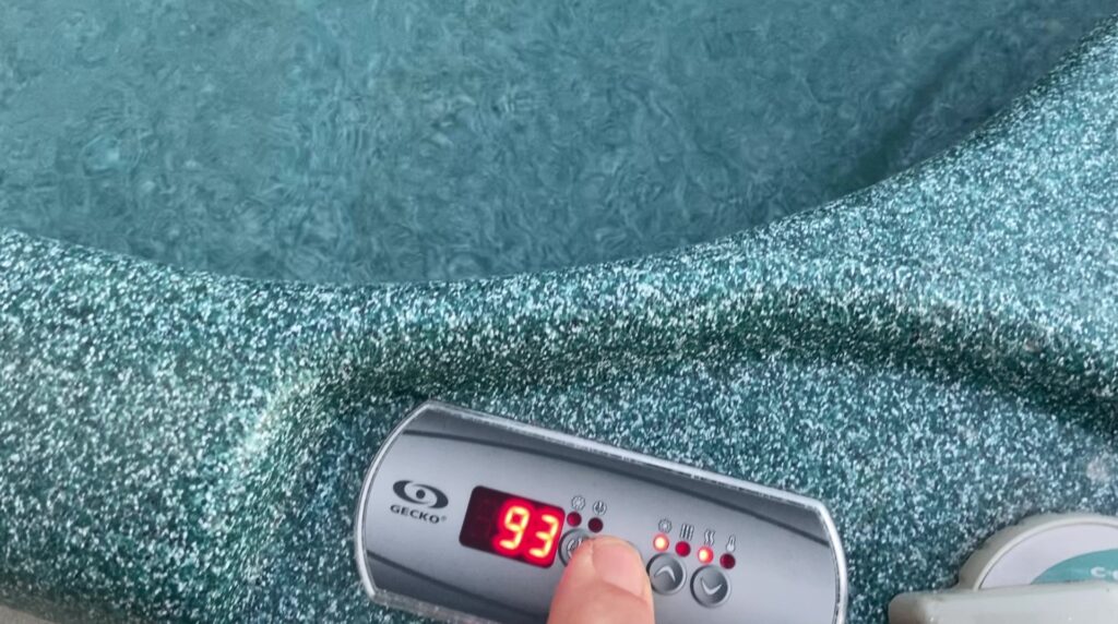
Good job!
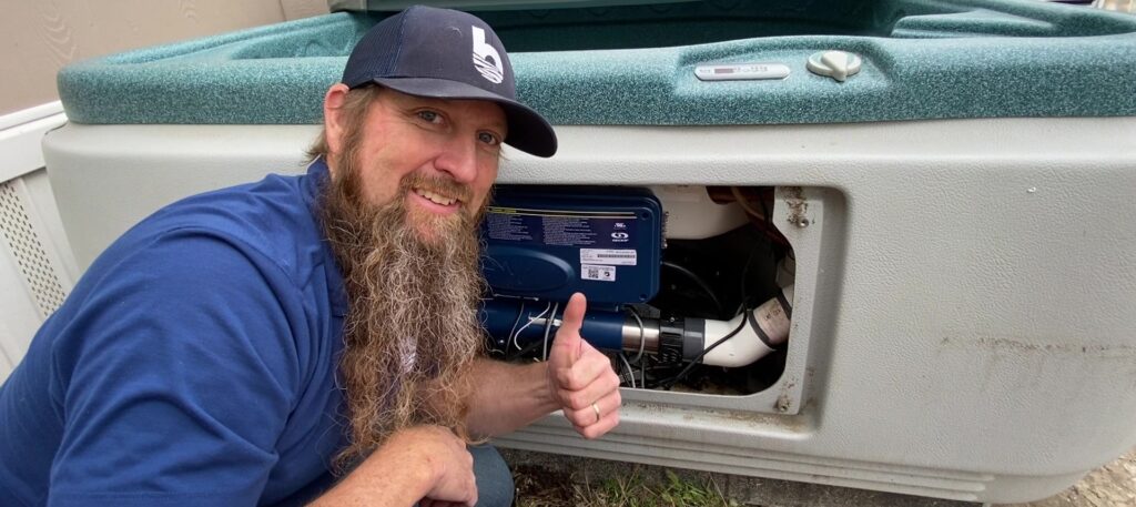
Watch the video here! “How To Retrofit Your Hot Spot and Solana Spa (1999-2005) with the Gecko IN.YJ-3 Control Box, KN-200-10P Topside and Heat.Wav Heater”
Questions about your spa? Contact us! We are the top Hotspring spa parts retailer on the web.
Call us at (805)541-9000
Text us to receive technical support
In addition to “How To Retrofit Your 1999-2005 Hot Spot and Solana Spa with the Gecko YJ-3 Control System,” we offer:
- Our Parts Finder which allows you to find exact-match replacements for your hot tub
- Free technical support that will allow you to maintain and repair your own spa accordingly
- Information regarding your products and their usage through our blog posts.
- Tutorials and assistance through our videos
- Follow us on our Facebook page
Our goal here at Backyard Plus is to help save you money by avoiding costly service calls for repairs that you can easily do yourself!
EditHot Spot and Solana Spa: How to Replace a Regulating Thermistor
Category: Technical Tips
Tags: hot spot temp sensor, solana temp sensor, temp control sensor replacement
